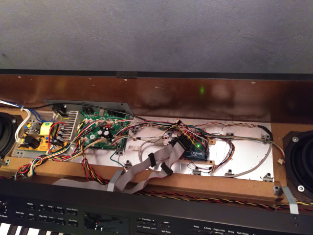
In this post, I write about a small do-it-yourself project I did end of last year: the repair of a defective digital piano I got. Below is a picture of the internals of the current state in which I replaced the defective parts with a custom programmed microcontroller.

Note: this should go without saying but just in case, before reading on, please be aware that this is not intended as a guide. Working with electrical equipment can be dangerous to you and your environment. If you still try to do anything of this you do this on your own responsibility and at your own risk!
It all started by purchasing a defective digital piano for a reasonably low price given that it did not work. My hope was that the problems could be fixed with reasonable effort. The first checks showed that the fuse was good. An on-board battery was empty. Unfortunately, replacing the battery was not enough to get the piano working again.
After some time without any further clues what could be wrong, I took this as a chance to get myself a used oscilloscope, which is a nice toy of its own.
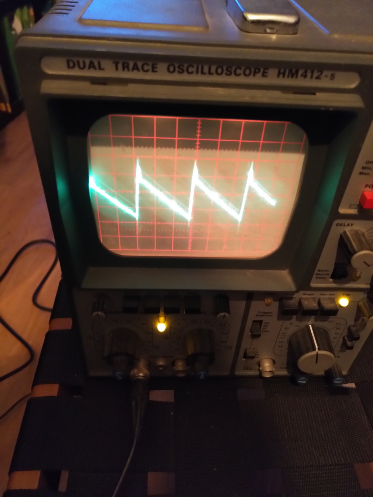
It showed that one quartz was also defective. I could replace the quartz and it indeed helped a bit in the sense that the piano now could at least enter self-diagnostic. The self-diagnostic showed that RAM and ROM were OK.

Unfortunately, I think I broke something else on the way to this state such that it was still not possible to get the piano working. The self-diagnostic failed while testing the main chip that was responsible, e.g., for the audio generation.
As a kind of “Plan B”, I switched to a different approach: replacing the defective electronic parts with a custom programmed microcontroller. The idea is to read-out the piano keyboard and pedals and generate MIDI messages from that via the microcontroller. These MIDI messages are interpreted with a computer for generating the audio, which can be fed back to the piano amplifier and speakers.
As computer I use a Linux tablet with QSynth for generating the audio. This has the nice side-effect that it can serve as a “touch panel” for the keyboard that can also be used, e.g., for showing learning videos.

I chose an Arduino Mega 2560 as microcontroller because I needed many I/O ports. Below is a picture of a preliminary state.
It took me some experimenting and I even disassembled the keyboard partially to get a proper understanding of the pin out etc. On the Internet, the maintenance manual for the keyboard is available, which also provides valuable information on pin-outs etc. However, I do not link it here because, as said above, this is not intended as a guide.

Eventually, I reached a state with which I am reasonably happy. The current solution also detects the “strength”/”speed” of a key press and puts that information in the MIDI messages.
Last but not least, I also connected the front panel buttons and LEDs to the microcontroller. Because I control all settings via the Linux-based tablet that I use for sound generation, I do not have any use for the buttons so far. However, I programmed the LEDs to display some “idle screensaver” like animation after some time when nobody is playing.

As I am mostly programming in Java, Clojure, Python, and even some JavaScript these days, it was a nice change to do something with a microcontroller that involved stuff like interfacing with GPIO. The source code for the microcontroller is available on GitHub.

You must be logged in to post a comment.